Engineering Details and Close-up Photos
While watching the construction of the
Ravenel Bridge I was attracted by
both the design and the construction process. When I took a photo of something
I did not understand, I asked for insights and many of you replied with a
description of the underlying process (e.g. tensioning cables, the concrete
slump test etc). Now with the unbuilding process, I am building a library
here of
unbuilding processes. The examples below describe the process
for removal of overpasses - which, as I watched, requires something equivalent
to surgical precision. I hope you enjoy these process descriptions also - and
as usual, if you have comments, clarifications or additions - then
send me
email
This is all about the surgical and dental skills of the Testa guys.
September 21 2005: Removing Stonehenge
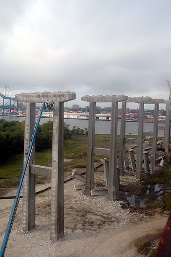
The Problem: There are a number of supporting columns linking the
Town Creek and Cooper River segments of the Pearman Bridge. How does
one remove these?>
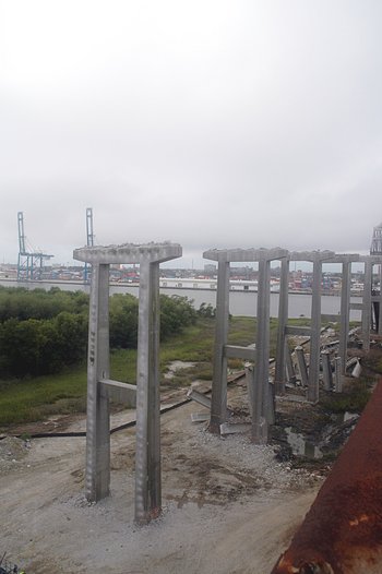
The problem can be readily seen here: a group of columns and caps that
have to disappear.
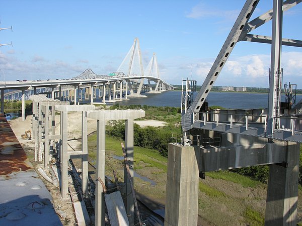
Rather imposing when viewed from Drum Island: looking east (left)
and looking west (right)


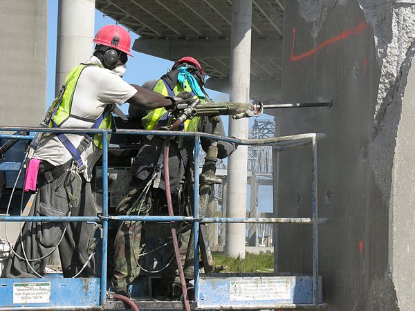
The idea dropping one of these concrete support structures
is similar to dropping a tree. The structural integrity of the lower
section of each vertical column is first compromised by chipping
away at the base (which has been previously marked -
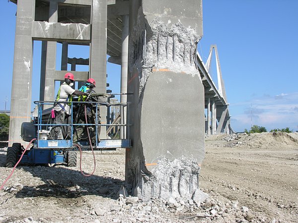
Holes drilled into the inner face of each column that accepts
an explosive charge that, when ignited, will push the structure in the
direction of the compromised base.
Practice makes perfect. This particular support will serve
two purposes. Dropping it vertically will be a test of the strategy used
to drop supports in the river. In addition, dropping it vertically
will provide a way to minimize the domino effect -
if all the segments fall in the same direction there will be
a possible domino effect which each structure leaning up against
its neighbor. To reduce the risk the middle structures is dropped
vertically by placing the explosive charges and then timing the
ignition to simply collapse the H-shaped concrete support.
The explosive charges for the east (to the right) and west (to the left)
H-supports supports are placed so that the strucures will fall toward this
center support. Here you can note the holes drilled up the entire length of
each vertical column of the center H-support as shown here from
Drum Island and from the Grace Bridge

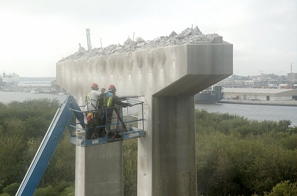
To get to the cap on the top of the columns,
a looooooong man basket is used
Here is a closer view of holes being drilled into the top cap of the
central support (that will be vertically dropped)
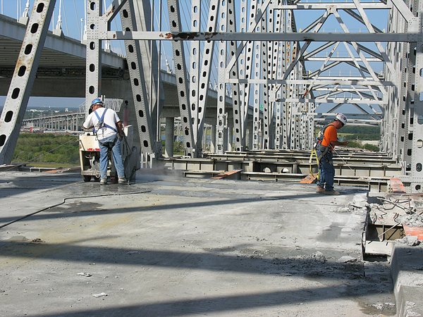
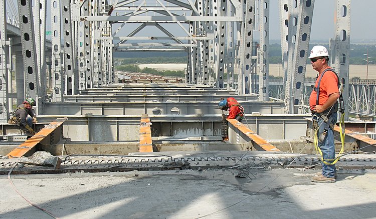
September 21 2005: Cutting roadway segments
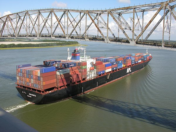
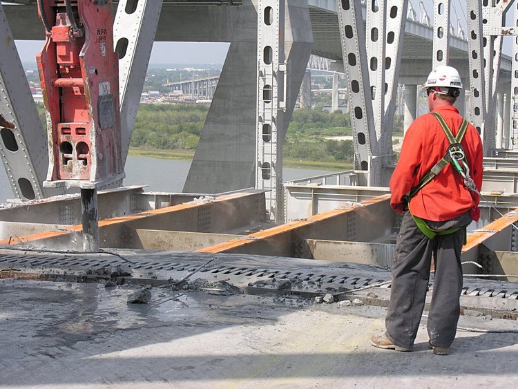
Meanwhile, managing the removal over the waterways is a different story.
Basically, the debris from the work on the bridge must not enter the water.
To catch the debris, a group of barges are used to span the potential
area of falling debris. While this is great in theory - the continued
use of the ship channel means that each time a ship enters the channel,
the barges must be moved out of the channel and work stopped.
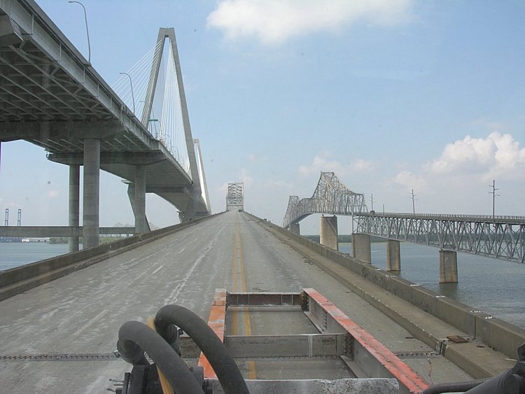
First, an overview. The Cooper River ship channel, the Pearman superstructure
and pair of barges is placed under the roadway to
catch any debris that might fall during the cutting and removal
operations.
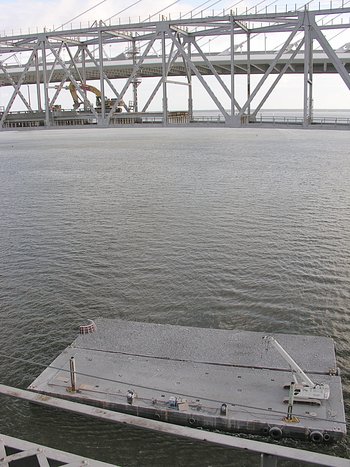
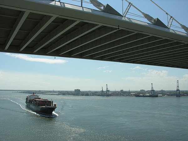
When a ship approaches the channel, not only must work stop while ships
pass under the bridge
but the barges must be moved before and then repositioned after
passage of the ships. Because of
Katrina, the shipping traffic to Charleston has increased dramatically
resulting in frequent work breaks. Entering the work area -
and leaving the work area -
Obviously, the rate of roadway removal is dramatically slowed
which creates a little chillin' time while the ship passes and
barges are repositioned
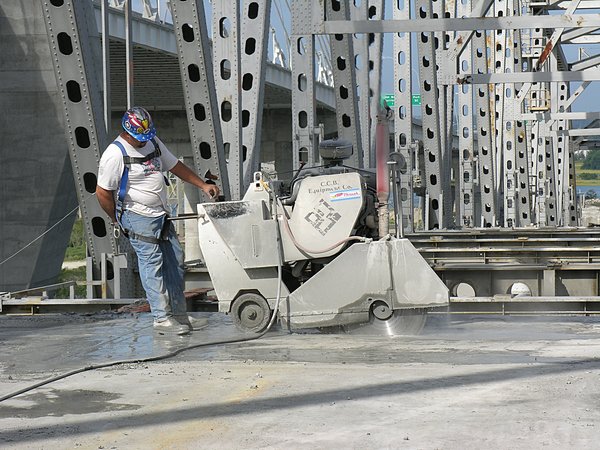
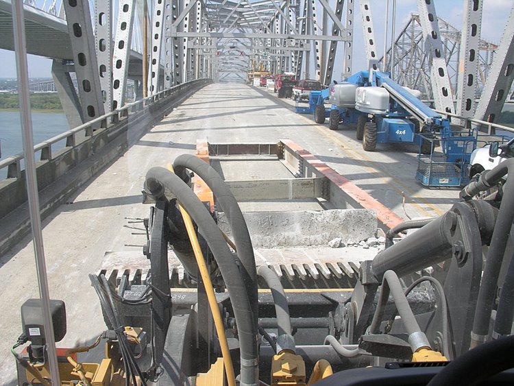
Segmenting the roadway into management chunks
What a surprise to see that removing the roadway is not simply
unpouring the concrete. It is cut in 7 foot segments by a
motorized concrete cutting machine complete with water cooling the
diamond tipped blade (I'm guessing about the blade).
Click for a video of cutting
(11 Mb quicktime)
Here Rich (working for Concrete Cutting and Breaking Inc.) is operating
a 120 HP, V-6 parapet deep-cut saw and is lowering the blade
onto the roadway surface to start a transverse cut (from right to left)
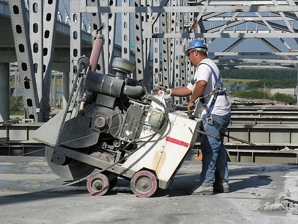
stopping at the edge of the roadway.
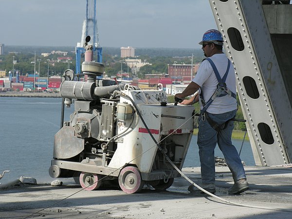
and then continuing from left to right
Once the transverse cuts are complete, two longitudinal cuts are made
dividing the strip into 2 segments.
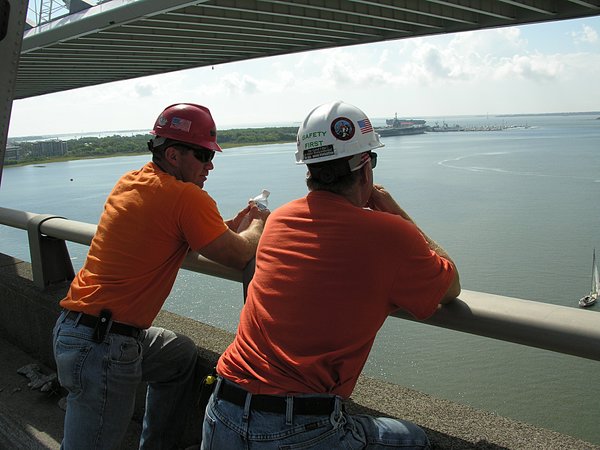
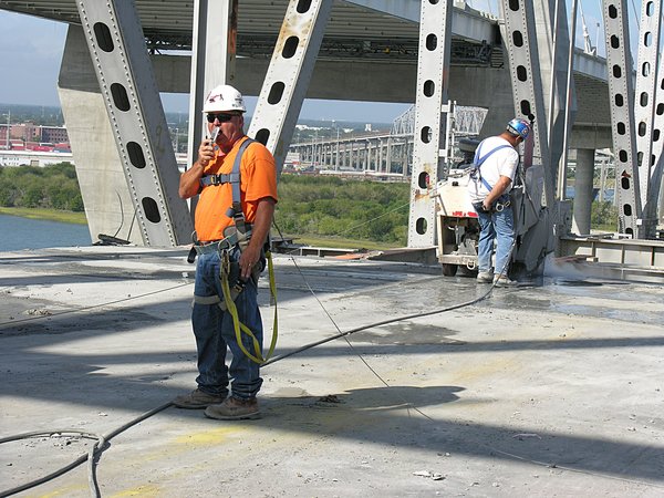
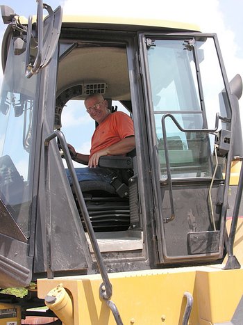
Here Pio is using one of his
modern communication devices to coordinate bridge work with
cargo ship passage up and down the Cooper River.
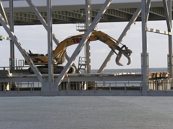
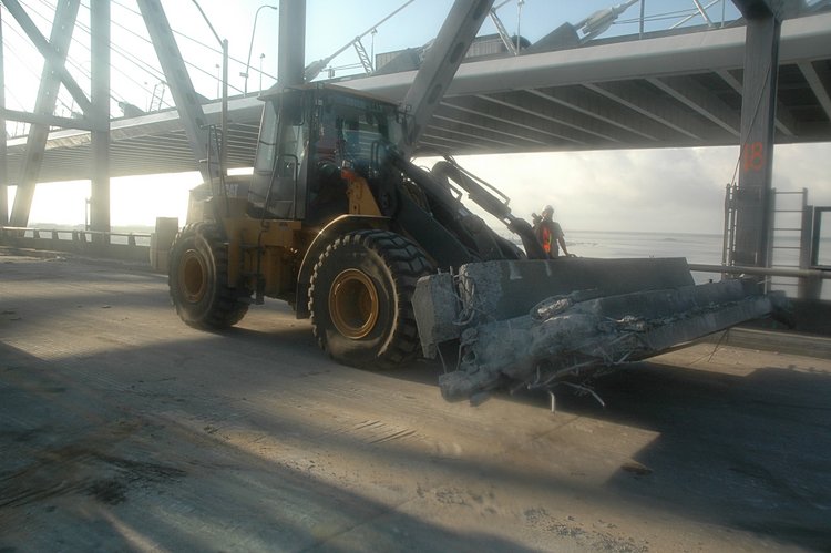
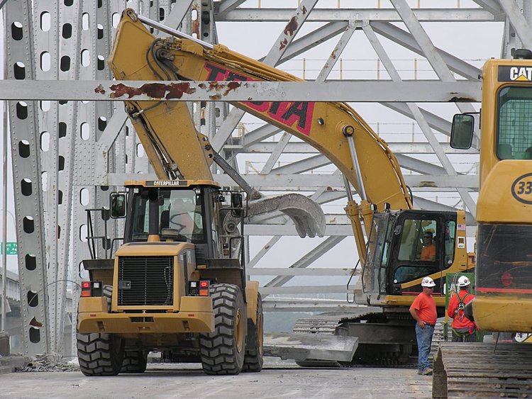
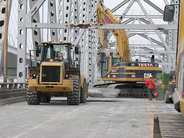
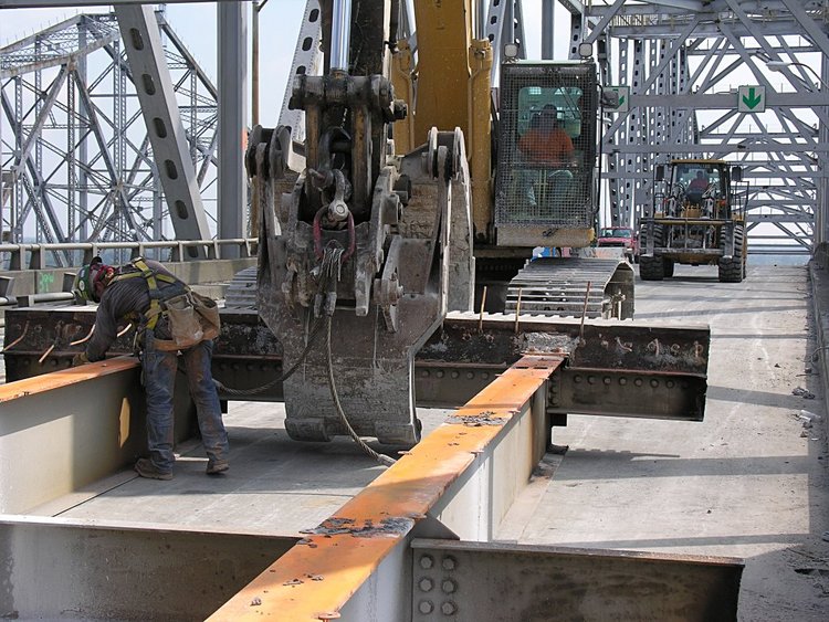
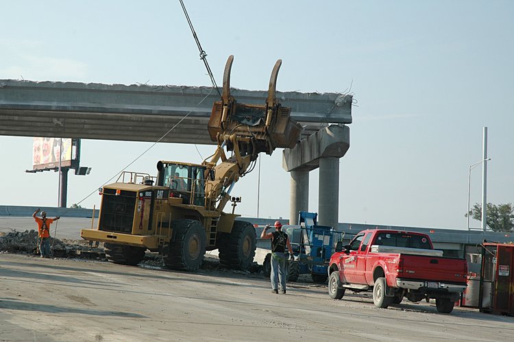
September 21 2005: Removing roadway segments
Watching from the Grace Bridge, here Pio, Michael, complete with his
CAT 345 grapple and surgical skills, Jim with his forklife and superb
driving skills, uproot each segment and transport it to the base of
the bridge for recycling
.
Click for a video segment(15 Mb)
Getting ready:
placing the grapple under the segement in order to take a small bite
Next, Michael rotates the segment into a vertical position
and completes the bite. Michael then turns around and places
the segment on Jim's forklift
Here he is rotating his 345 with a concrete segment in his grapple
He then lowers the segment
Gently putting it to sleep
Later Jim approaches the segment from the left
and Michael lifts it enough
for the forks to support the roadway segment.
Then its off to the recycling area at the base of the bridge.
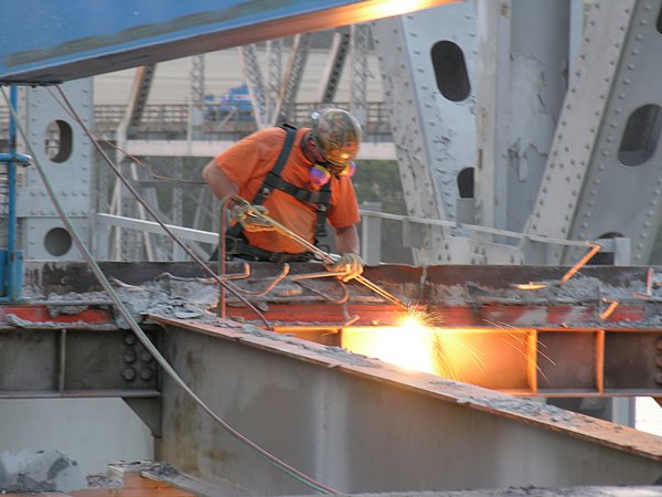
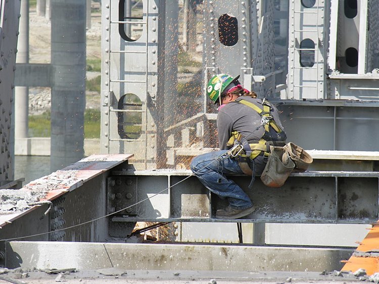
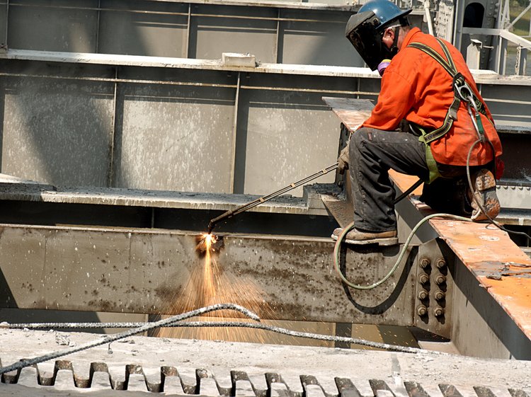
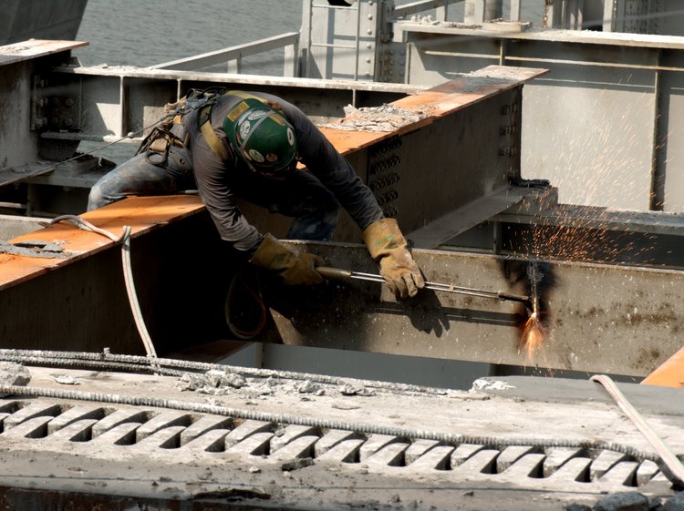
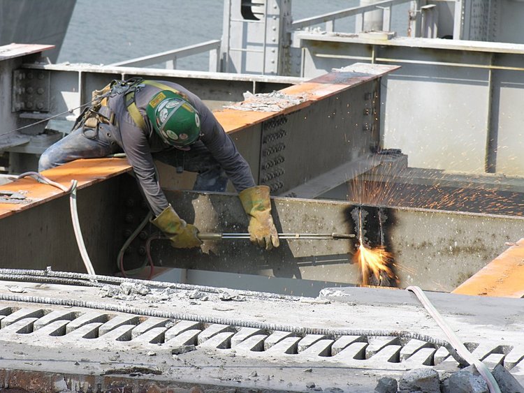
September 21 2005: Cutting Girders
Once the concrete roadway has been partially removed, the torch guys
work their magic - cutting the end giders in two places so as to make
3 pairs of longitudinal girders. Once all the roadway has been removed,
each pair of girders will be extracted with the grapple and then removed
to the recycling site.
The cutting torch has a very long handle so that the operators can
reach difficult places for cutting. And how does the torch cut? The gas
mixture is oxygen and some fuel such as acetylene. When there is an excess
of oxygen, the residual oxygen is available for burning the metal being cut.
When there is an excess of fuel over oxygen, the torch is used to anneal
two surfaces. Here you can see the worker cutting through the steel beam.
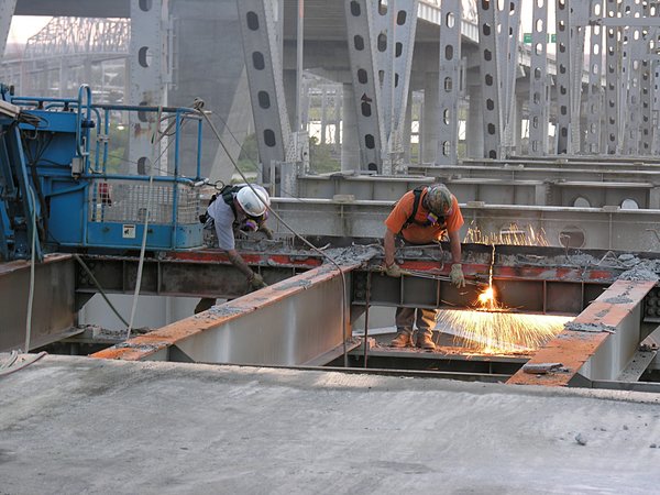
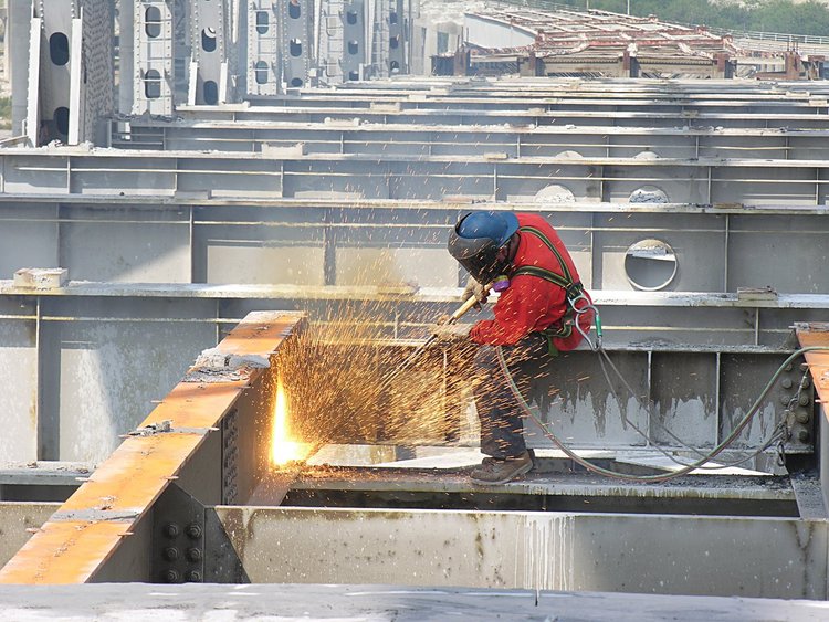
With both guys working - its like the 4th of July

and here, you can see the flame cutting through the beam and exiting on the
opposite side
September 20, 2005:
Tooth Extraction and Root Canal jobs
on the Pearman roadway.
I continue to be impressed with the skill and art of these Testa
surgeons and dentists. Here is the story of tooth extraction and
a root canal procedure. It starts by a walk from the Mt. Pleasant
side of the Pearman Bridge.
The basic procedure is to cut the concrete roadway into
7 foot strips, remove them and then remove the underlying
girders. Here is a segment of roadway being placed on the
forklift (driven by Jim) by the 345 grapple, Michael (whose wife
Tina continues to encourage me with these stories).
Here Michael's 345 (right) releases the concrete segment onto Jim's
mega-forklift (left) and off Jim goes to the recycling center at the
base of the bridge (Coleman Blvd).
Jim gets a lot of practice driving backwards
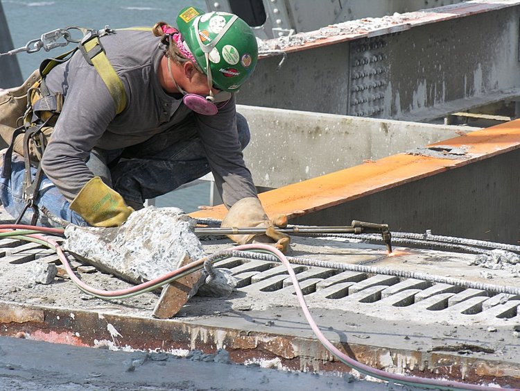
Here is Richie - one of the skilled surgeons, who, with a torch,
can cut anything

and Nugget (Mike) who has yet to tell me his story
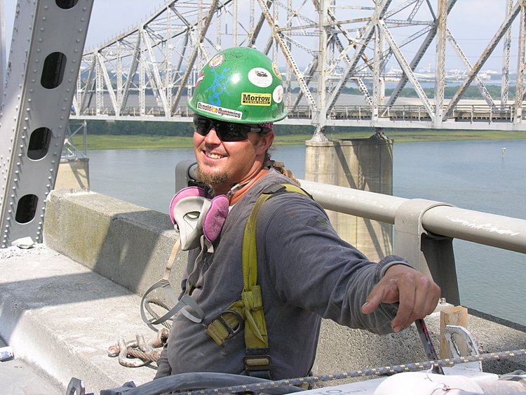
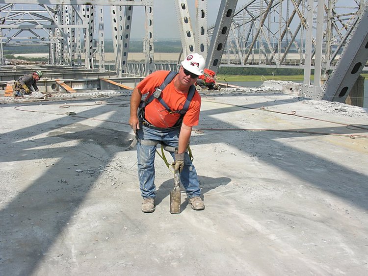
The extraction process starts with Mike's jack - which hammers
a channel along the length of the expansion joint

and Richie looking on - To see this live,
click here (20 Mb
quicktime video)
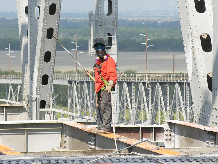
After the channel is prepared, Richie suits up for a bit of cutting
while Jim enjoys the comfort of his forklift

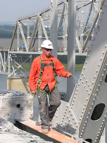
Torch (unlit) in hand, Richie walks out on the right girder to cut elements
that bond it to the bridge structure
while Nugget is cutting away on the left side
All the time - Pio is watching and in communication with the home office
Richie cutting a crossbeam
Nugget is making the first cut to sever a crossbeam
and here, Nugget is making the 2nd cut to sever the brace between
the two girders
while Richie is making a July 4th display with his cutting
Next, Nugget cuts the expansion joint and literally extracts a tooth from the
expansion element. Another tooth is extracted and this divides the roadway
girder structure into three components.
Meanwhile, Michael and Jim are just chillin' a bit while the cutting
continues.
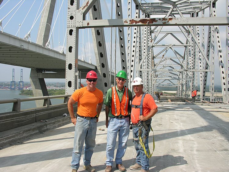
And as you can see, Pio is holding one of the teeth - root and all
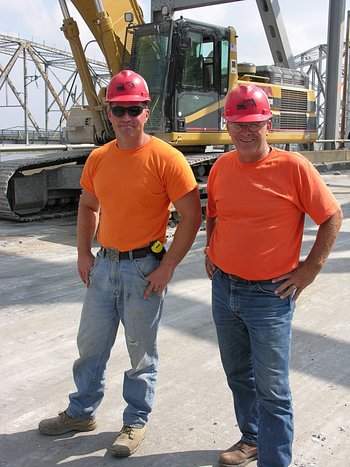
and a rare photo of Michael, Frank and Pio. Jim takes better photos
than I do
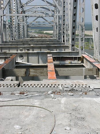
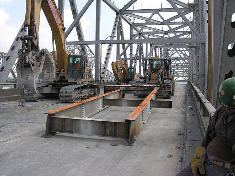
Here are the middle and right girder segments - what we refer to
as the root canal

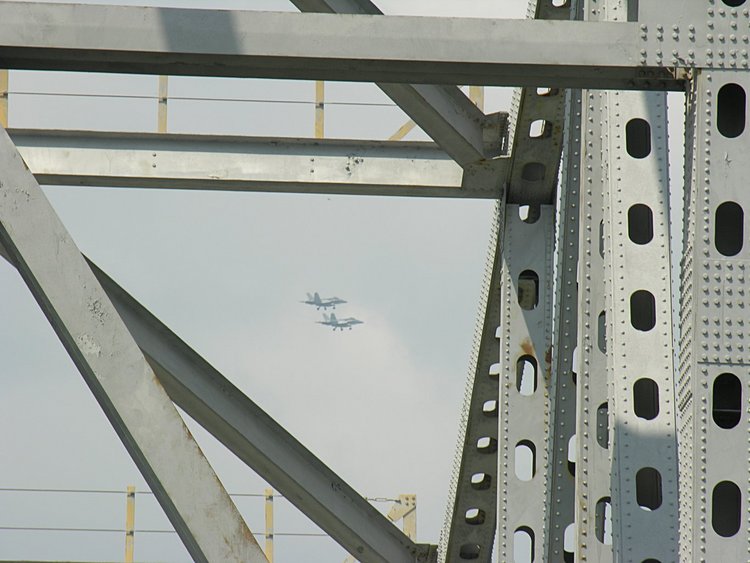
and to add to the entertainiment two F-somethings have their landing
gear down - I suppose to land somewhere
Michael with his grapple, reaches under the expansion joint and
pulls it up
Oops - it did not want to cooperate - so just as in the dental
chair - a bit of investigation is in order.
Richie goes back down to cut a remaining bolt - that I suppose was
a surprise
Richie watches as Michael takes another pull - and
up comes the middle pair of girders
now Michael pulls the girders backwards and onto the roadway
and gently places it on the road. For a video of the
extraction process
click here
(30 Mb quicktime video)
This is now what the girder structure looks like with one root canal
gone
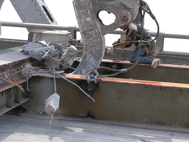
Nugget uncouples a shackle tied to one set of cables from the girder
pair while Michael is
driving the grappel and Jim is driving the mega-forklife
here Nugget is removes the other shackle that uncouples the other cable
and Jim drags it down to the Mt. Pleasant reprocessing plant. Lots
of practice with backwards driving
a bit more backing up
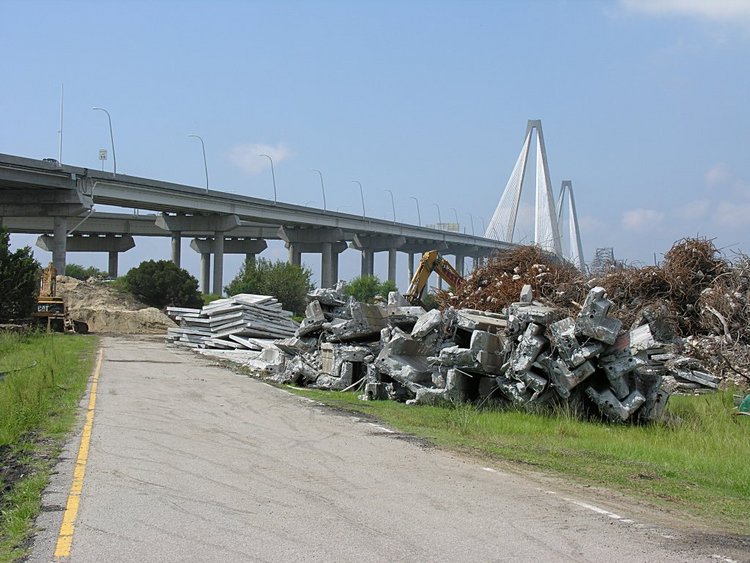
and a nice view of the Ravenel Bridge
and deposits it in the recycling and reprocessing plant.
Note the stacks of 7 foot roadway segments. Here
concrete is separated from rebar, girders are cut and a lot of
other stuff that minimizes that waste.
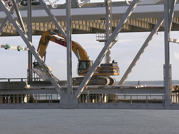
While removing bridge sections over Drum Island were understandable, I did
not understand what was happening at the point where the steel superstructure
rested on the concrete support. On Sept 3rd I took some photos - but
the overall idea escaped me. Today (Sept 12th) I took additional photos and
with these data, Ken Canty showed me what was happening. Here is the story.
September 3 2005:
Pearman Superstructure Preparation
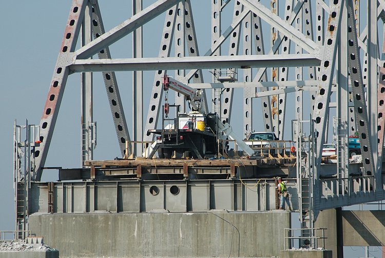
As roadway is removed from the Pearman bridge that spans Town Creek,
there is less downward stress on the supports. Consequently, the
support might have a tendancy to rise vertically, placing a significant
new stress on the pins that tie the steel superstructure to the supporting
concrete structure.
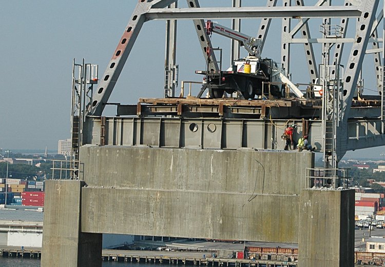
Here is the end of the Pearman over Drum Island -
and work platform
for securing the end of the Pearman superstructure

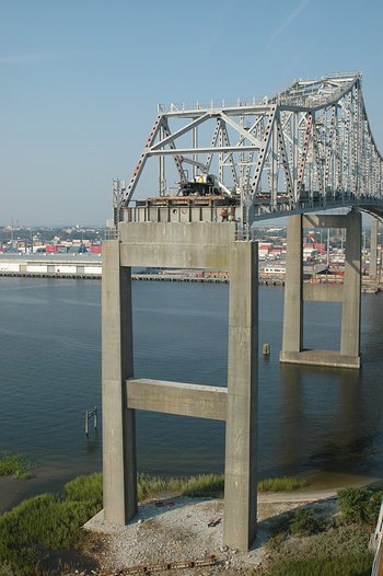
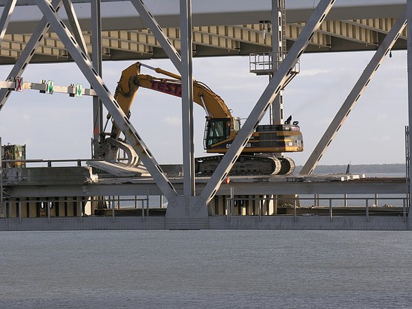
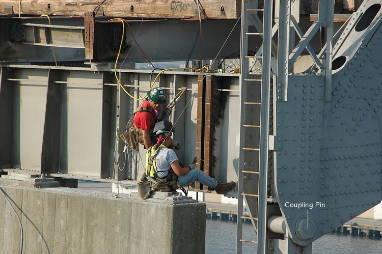
A closer view of the work
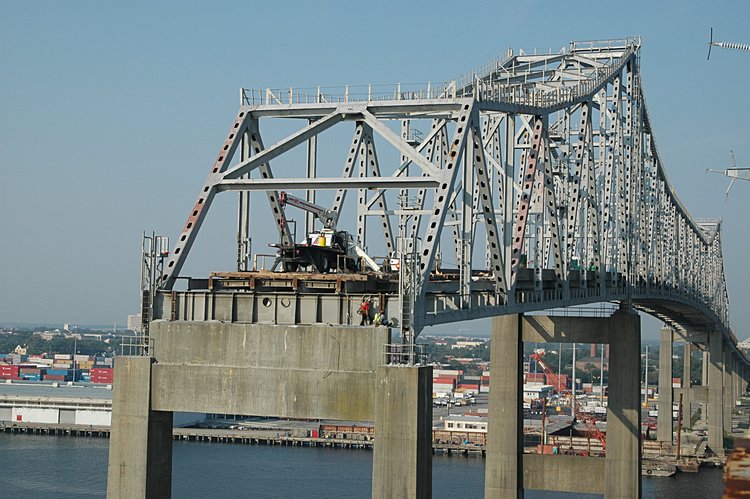
On the left you can see a pair of vertical channels with two horizontal angle
iron brackets. On the right, the guys are preparing to add the two
horizontal angle iron brackets
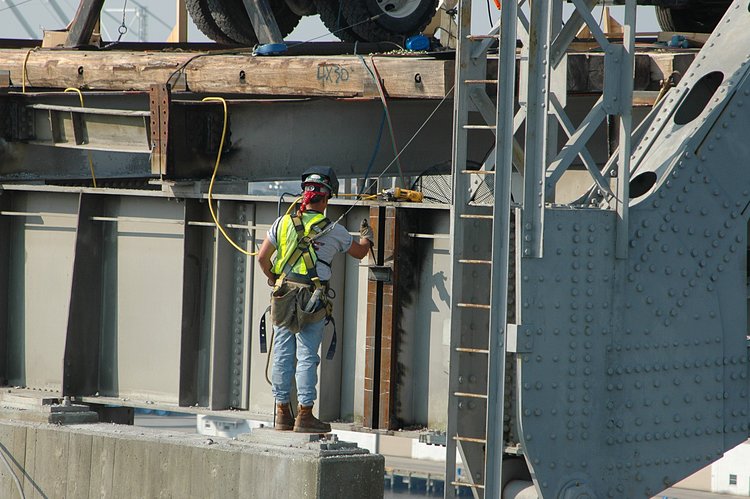
Preparing to weld (with your curious eyes, you can see the welding rod in
his right hand)
About 30 min later - last weld on the top bracket
Cleaning the weld - but the big question for me is what is the purpose of
this addition?
September 12, 2005:
A week ago I was puzzled by the work at the eastern end of the
superstructure. Testa was placing the vertical channels and welding
angle irons. Well here, it seems they were making what I would call
a tiedown - brackets that bind the bridge girder structure to the concrete
pier.
Ken Canty and I talked about this and Ken helped me to understand what is
going on. If you look at the right side of the concrete support, you will
see a pin that couples the steel superstructure to the concrete support.
(Scroll up 3 photos to see a closer view of the pin)
As the concrete roadway is removed the entire bridge structure loses
weight - sort of a Testa-diet. The tendancy, then, is for the concrete
support to rise - since for all the time since the bridge was built
the concrete support has had the weight of the bridge on it.
So, if enough weight is removed from the bridge, all the stresses will be
concentrated in the two coupling pins. To assist the bridges integrity,
the steel superstructure is couple via the tiedown cables (see the beam
that link the short beam resting on top of the transverse girder (on
either side) with a similar beam under the concrete cross
member.

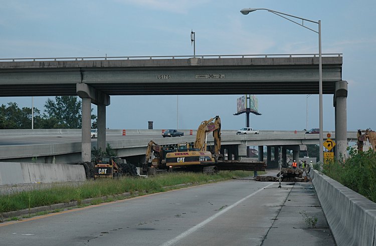
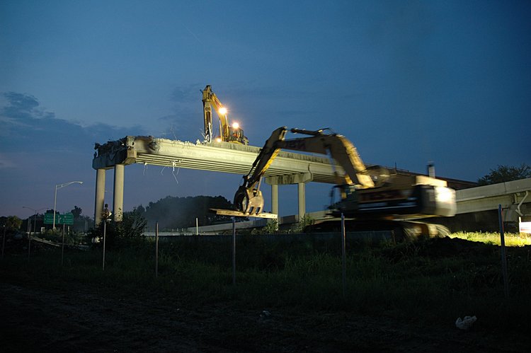
August 12, 2005: Unbuilding the I25-Exit 221b overpass
What an adventure - to watch the unbuilding of the overpass. Here is a
photo-description of removing an elevated section of highway. There
were two challenges: how to take meaningful night photos and the
understand the girder removal process. For the first, I must thank
Stephen SetteDucati for some
quick lessons in night photography.
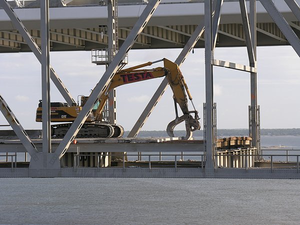
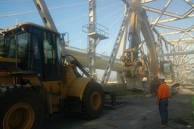
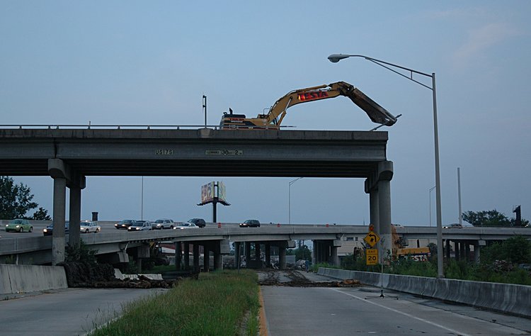
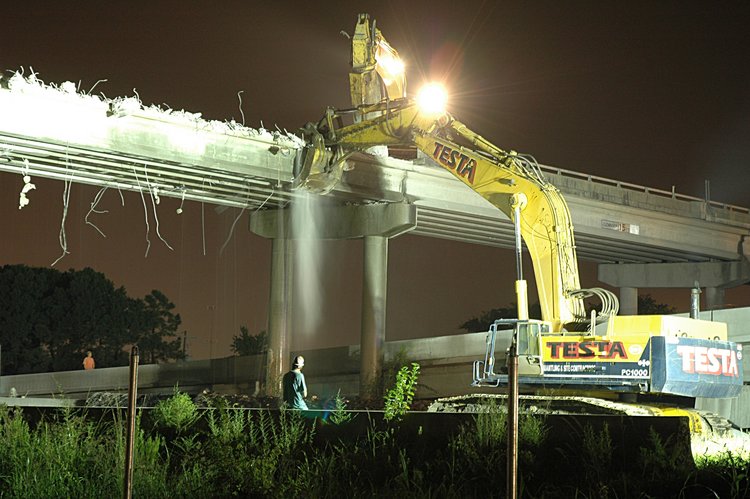
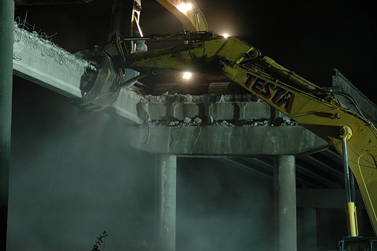
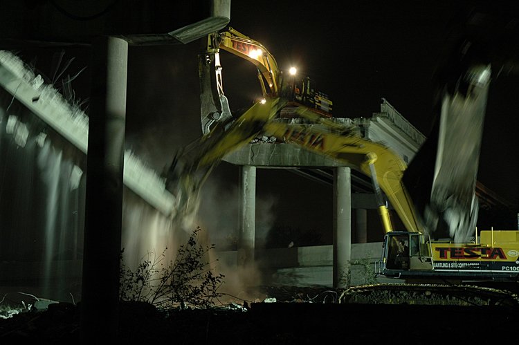
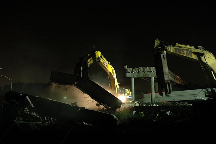
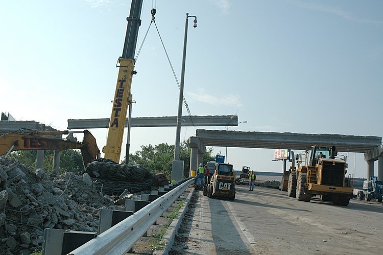
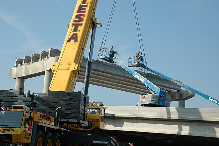
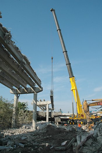
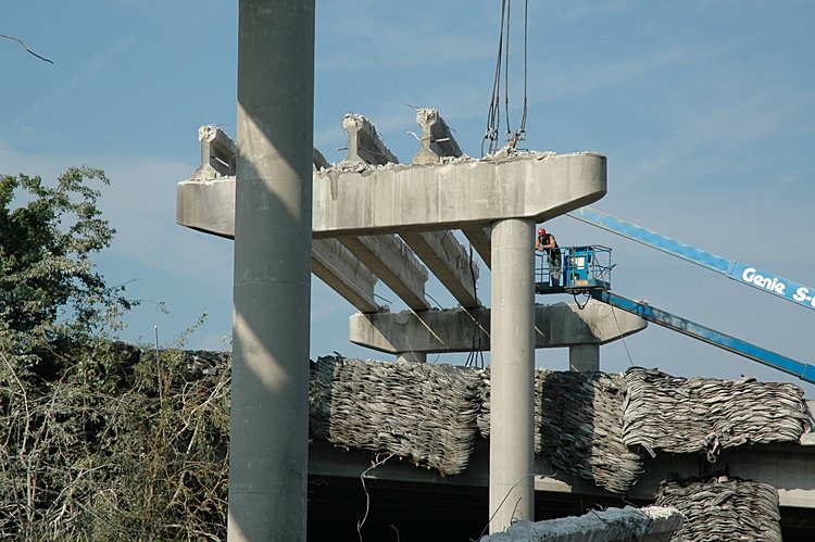
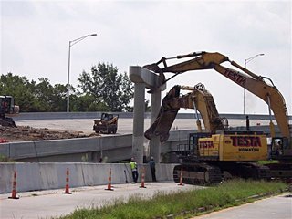
The engineering challenge is how to remove the overpass girders without
destroying the roadbed underneath. First the roadbed underneath the
overpass is covered with a blanket made of old automobile tires - to
absorb the shock associated with falling debris. In addition,
I learned from tonight's
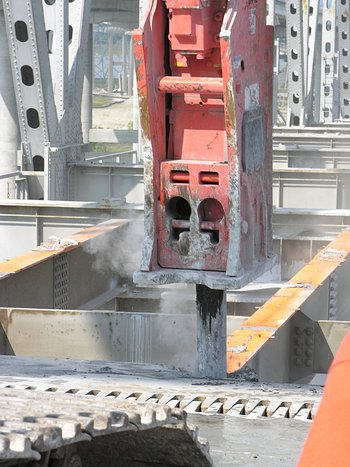
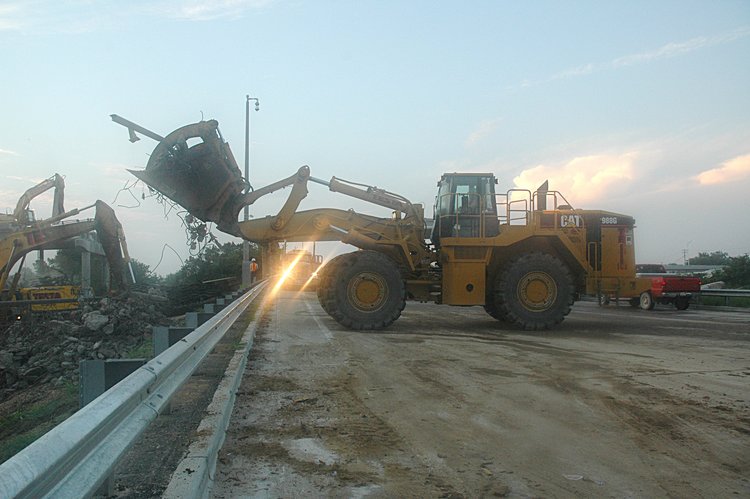
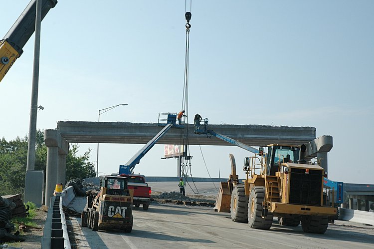
adventure that there are two classes of machines are used: one with a hydraulic
shear for cutting the concrete girders (including the embedded rebar)
and the other, I believe is a hydraulic grapple for
holding and stabilizing a girder while it is being cut with the shears.
It also plays a role in picking up and transporting large chuncks of debris.
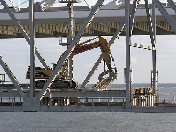
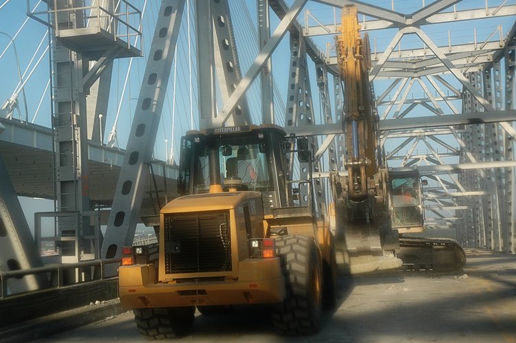
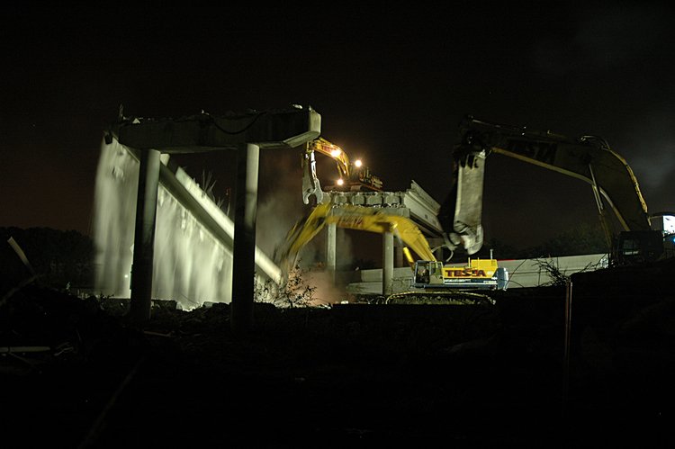
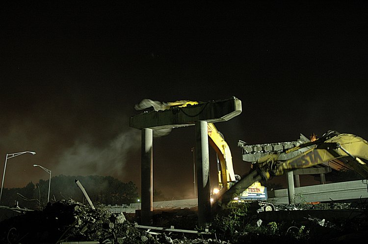
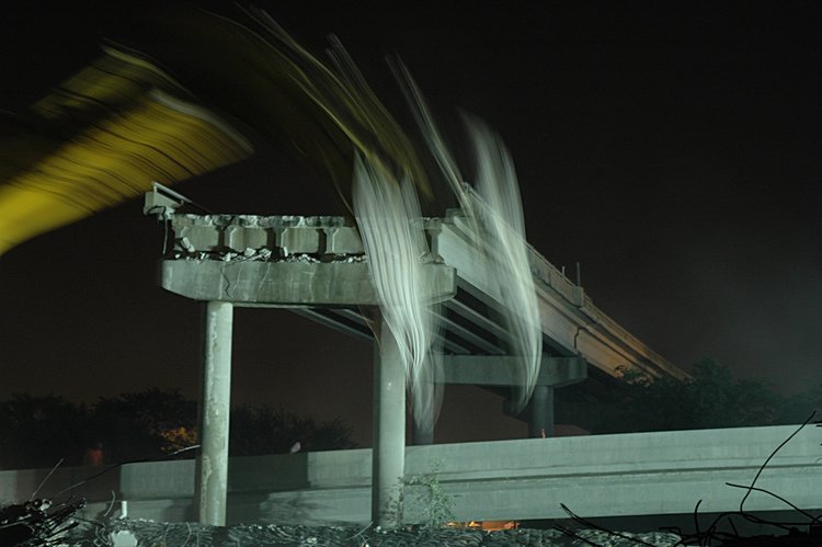
The overpass is supported by pairs of vertical columns (piers) with a
cap on top. The space between caps is spanned by some sort of girder -
steel or prestressed concrete. The roadbed is then built on top of
the girder structure. To remove the overpass, it seems that you just
reverse the process - roughly following this recipe:
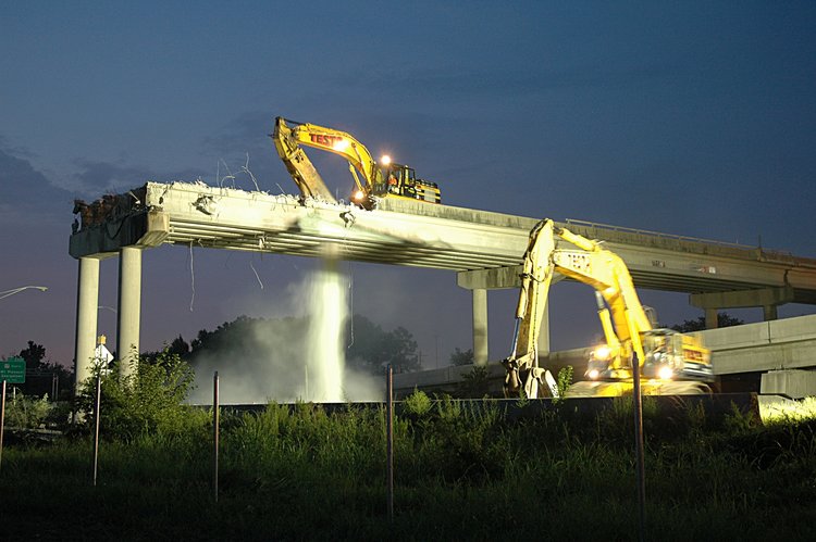
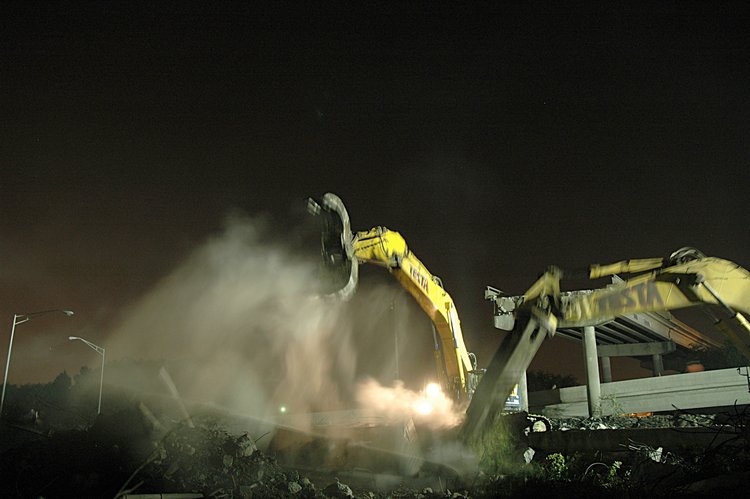
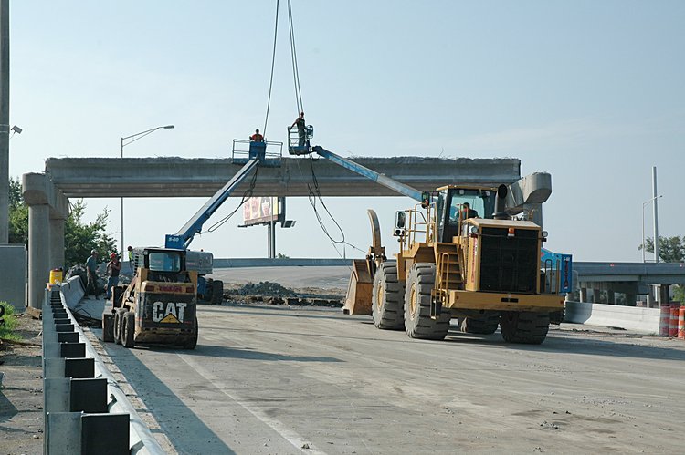
- Remove the aluminum rails
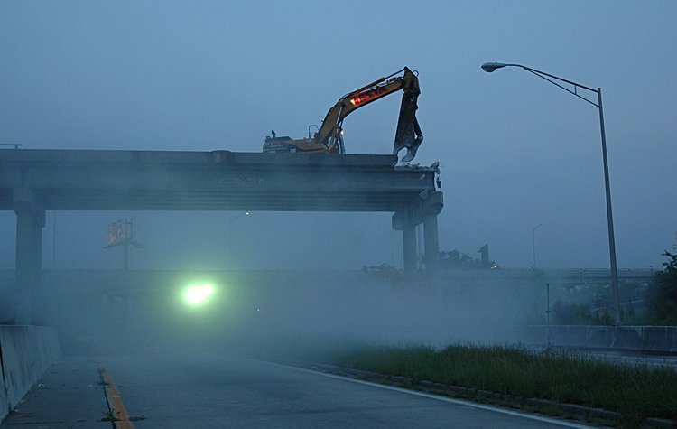
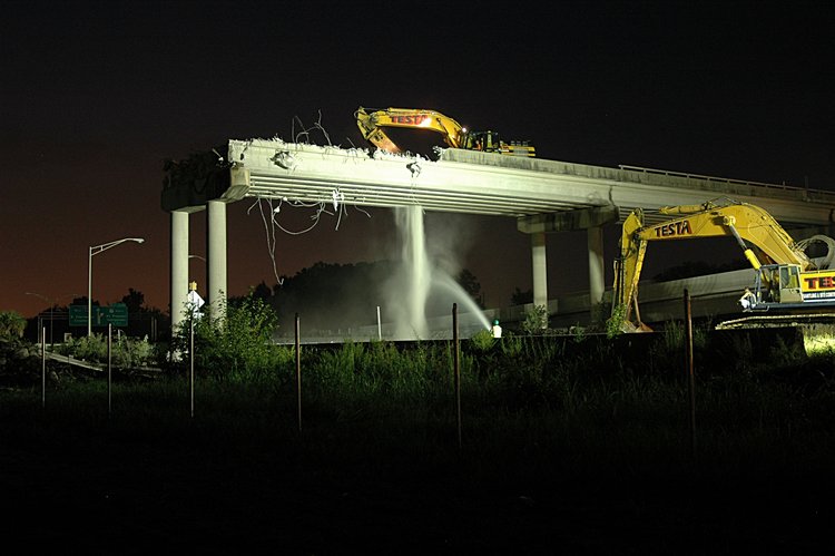
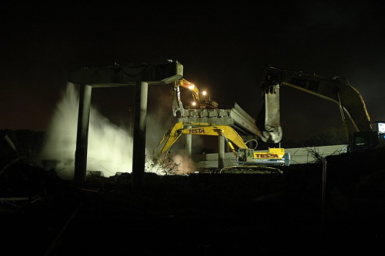
- During the removal process, water is sprayed in the direction of
the work area to minimize dust.
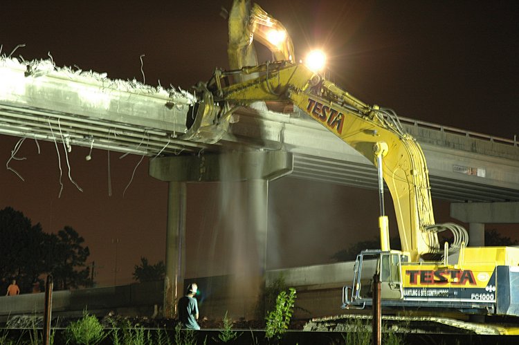
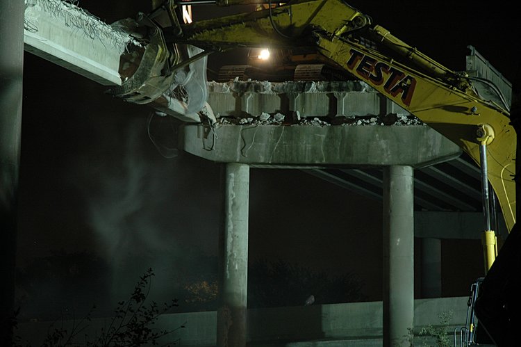
- Remove the side barriers
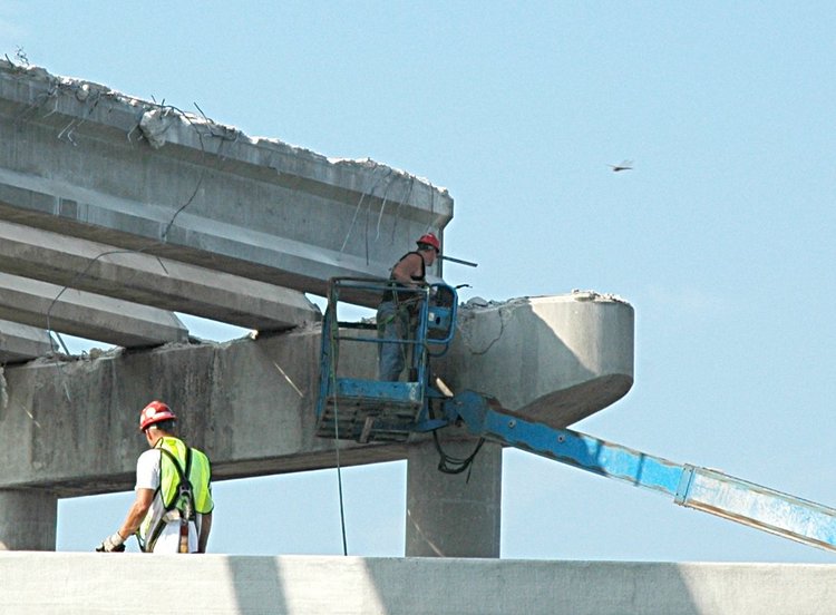
- Push through the roadbed floor between the beams
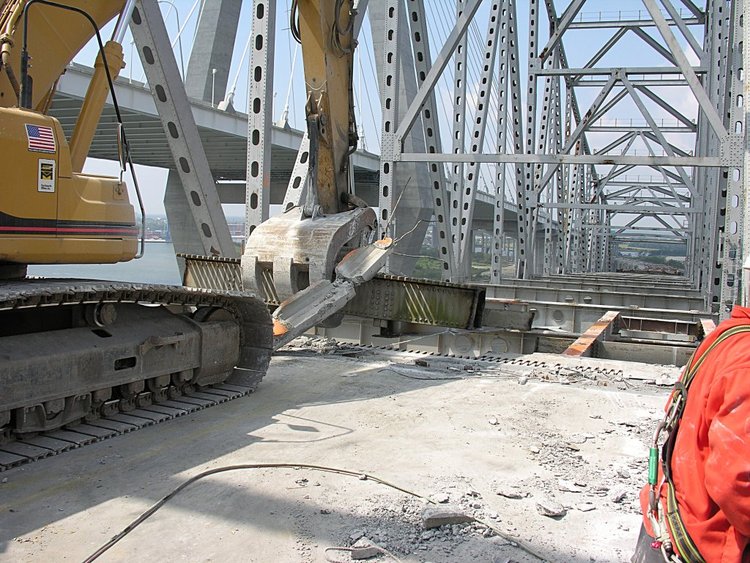
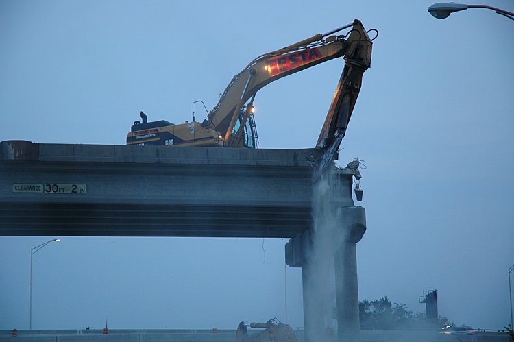
- When all the roadbed between beams is removed, then one machine with
claws or grapple (I call it a whatever until one of you tells me the
proper name)
holds and stabilizes the beam close to one of the supporting caps. At the
same time another shearing machine (giant sissors) cuts the beam near the
edge of the pier - small bites, starting at the top and finally cutting the
last chunk (concrete with embedded rebar). The grapple machine then
slowly lowers one end of the beam until the rest sort of falls off the
other supporting cap.
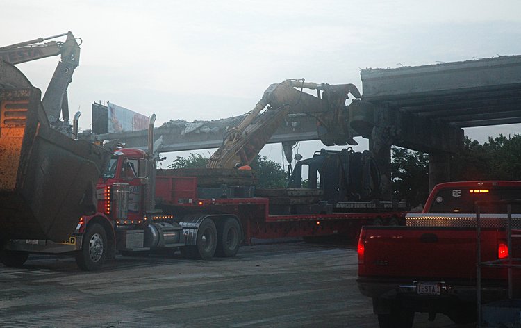
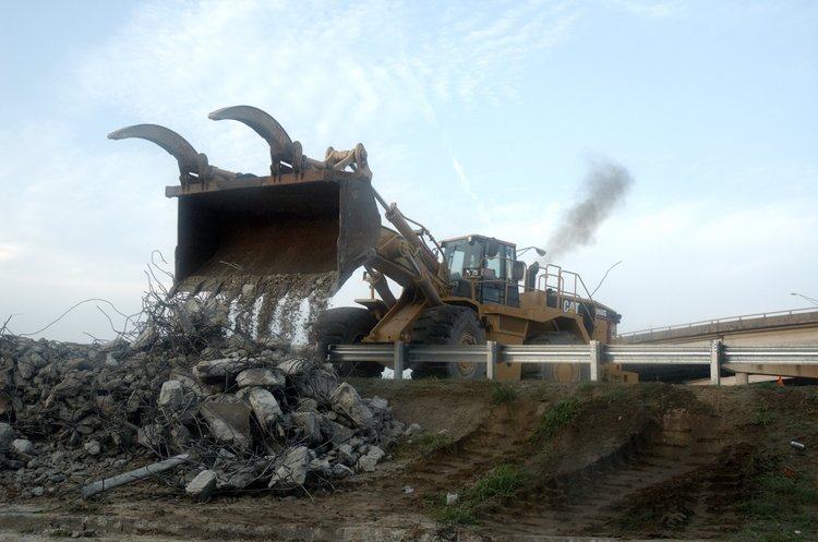
- The operators of these machines then clean up the girder debris
and and move it to the side for later reprocessing. The rebar will be
separated from the concrete and pretty much everything recycled. Large
segments of concrete will be transported to the Navy Shipyard and placed
on barges and then deposited at artifical reef sites off our coast.
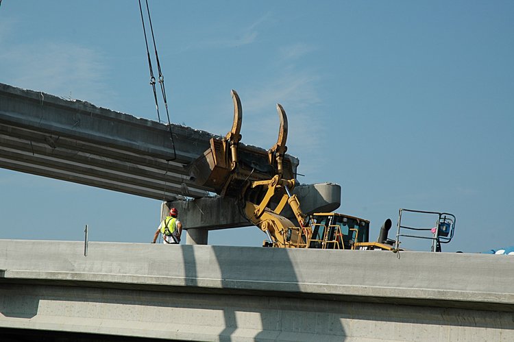
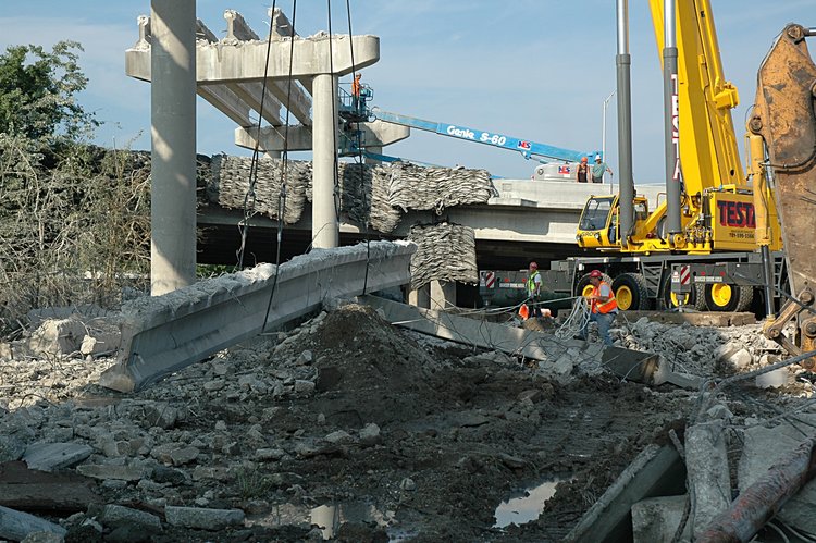
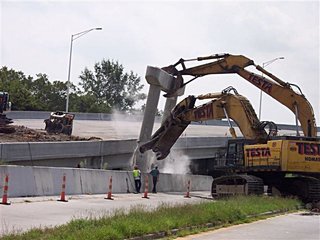
- When all beams are removed, the pair of near piers and cap are pushed over
with one machine cutting the base of one column while the claw machine
gently pushes the entire struture over.
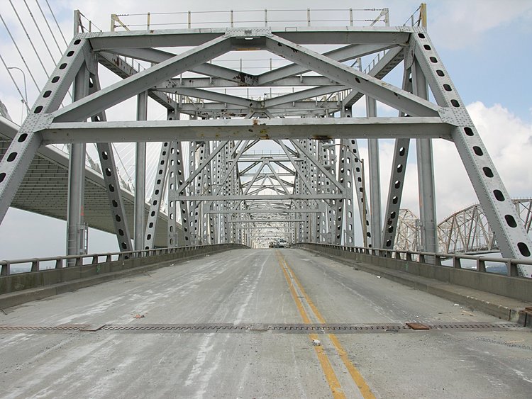
Here is the overpass with side rails, supporting piers and caps -
a before view
Removing a segement of the side aluminum rail
Cutting and pushing the edge barriers over the side - chunk by chunk
starting on the north side
A larger chunk on the north side
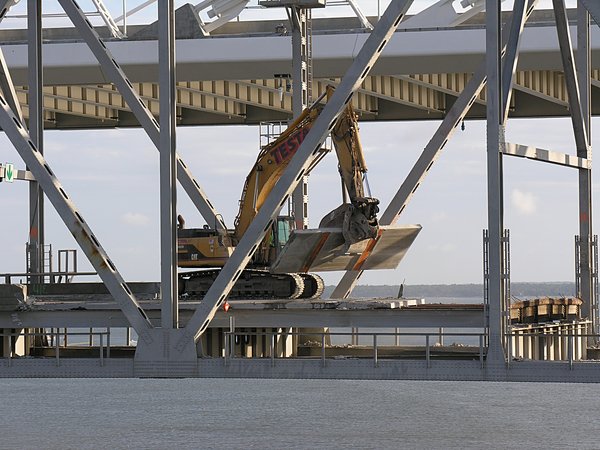
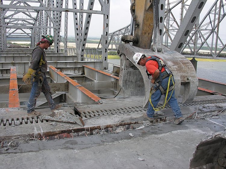
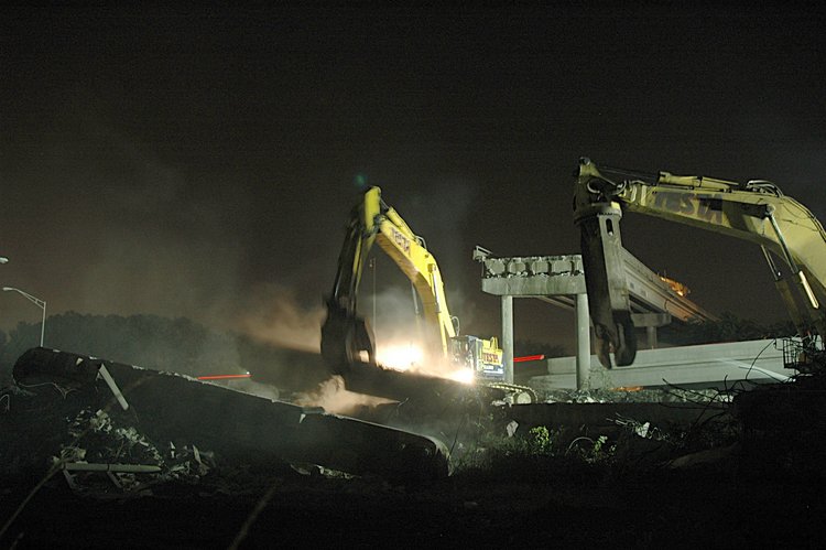
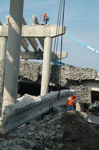
Then working on the south side - punching through the areas between girders
More punching through the floor between girders
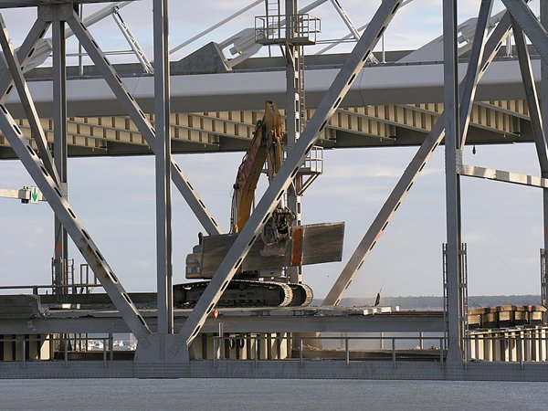
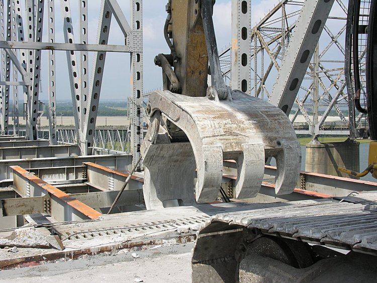
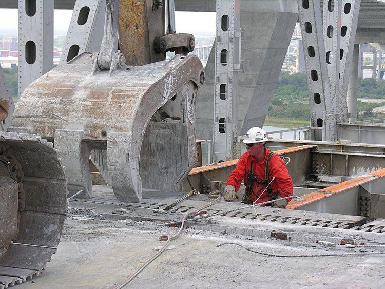
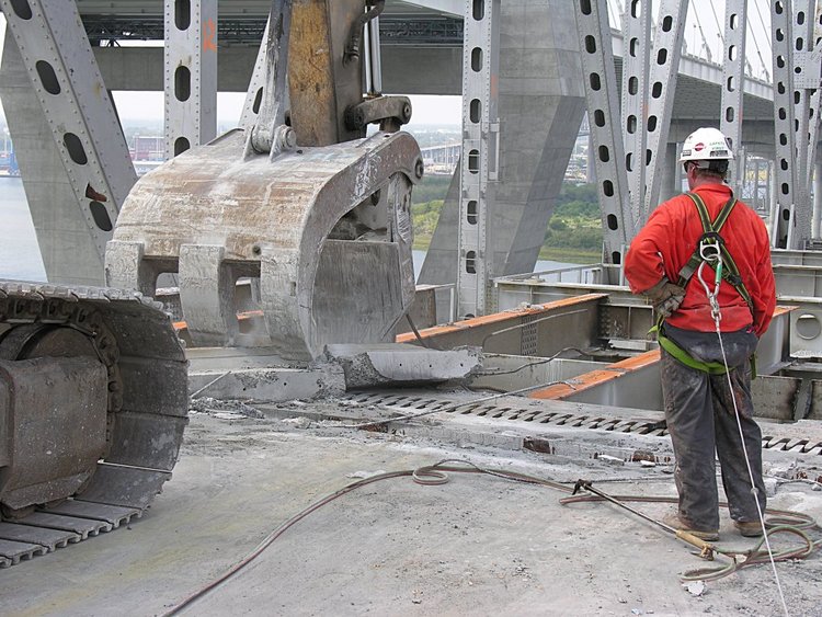
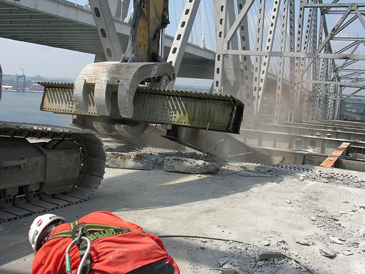
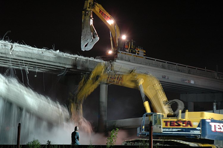
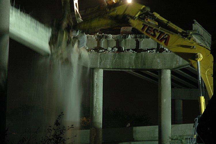
While holding the girder with a "whatever" the hydraulic shearer takes bites
out of the first edge girder at the edge of the cap - weakening the area
over the pier cap
Shearing in action
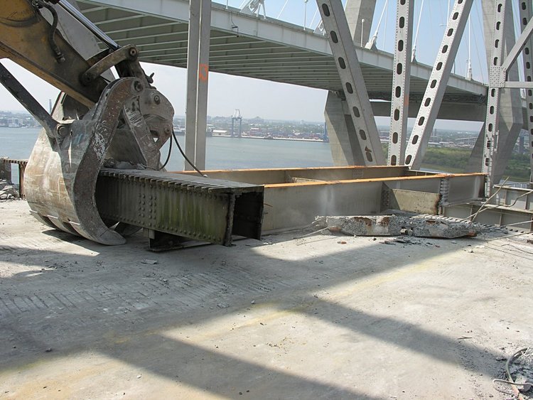
Then gently lowering the first girder

and a little cleanup action
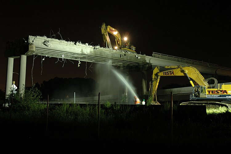
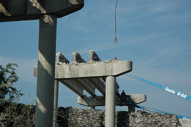
After some time (about 2 hours) removing the final girder:
continuing the hold and shear process
a deeper bite
and the final bite
and gently lowering the girder
down
down
to a temporary resting place - where cleanup begins again
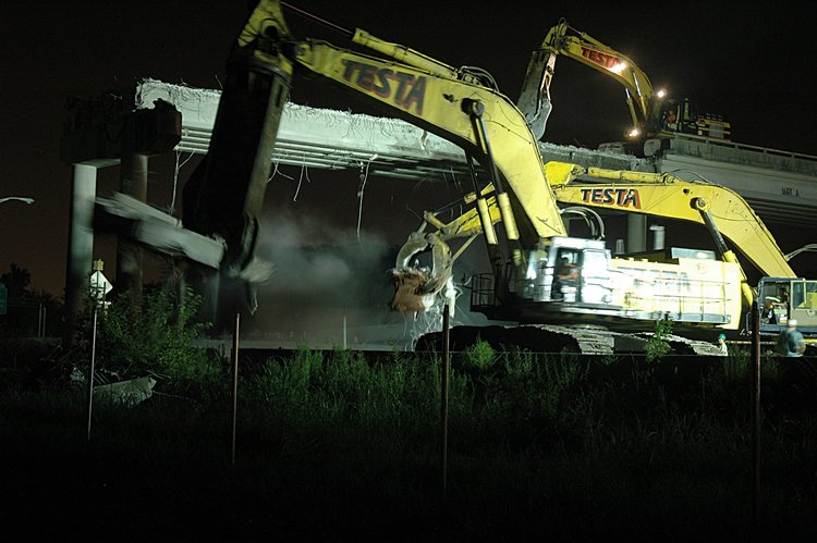
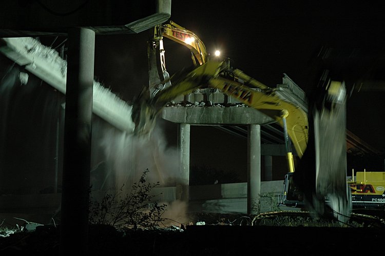
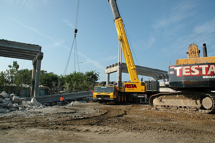
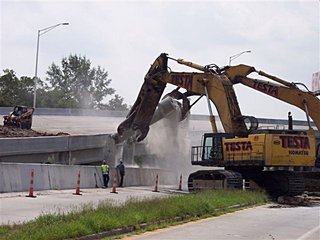
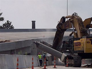
Now that all the girders have been removed, the last step is
gently pushing the pair of piers and the cap over
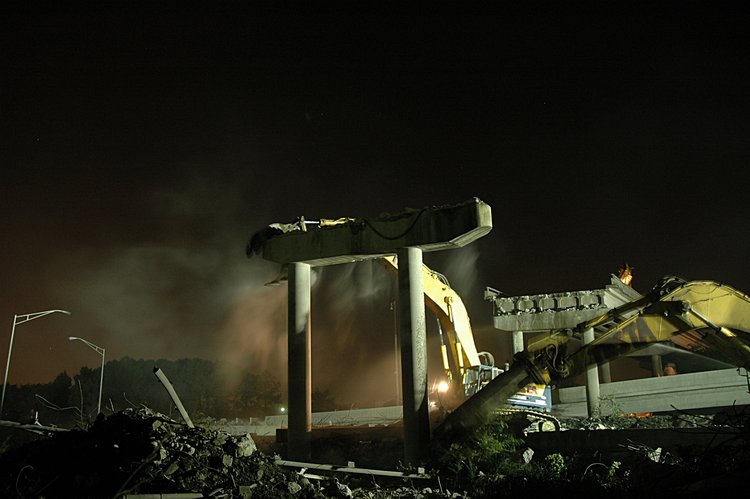
The left machine is biting the cap while the right machine is right
machine is biting the base of the right column.
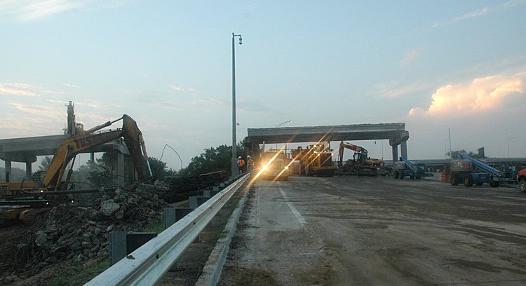
Jaws wide open after a gentle nudge
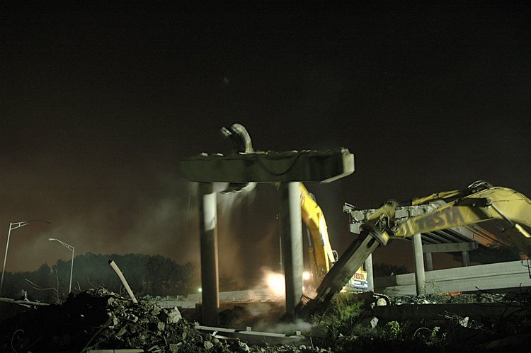
And then gravity does the rest of the work
and cleanup
and more cleanup
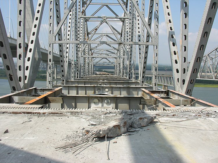
and I went home after admiring the clean interface between the next
set of girders (spanning the I-26 on-ramp) and the supporting cap.
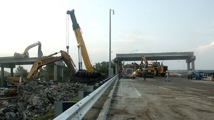
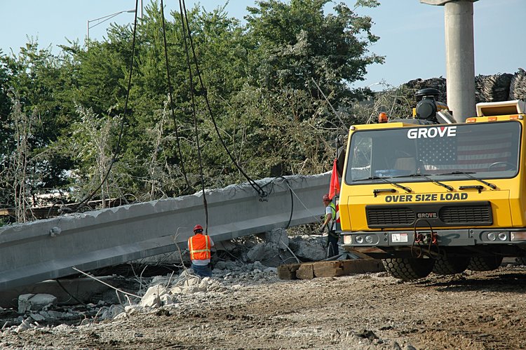
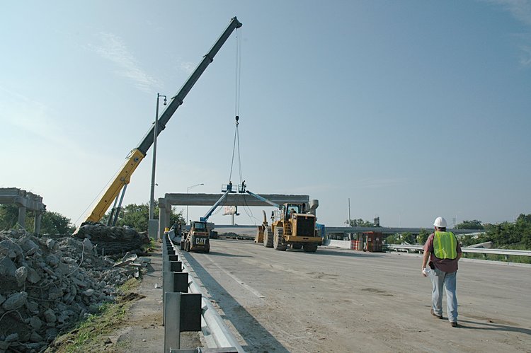
August 14, 2005: Lifting girders from the I-26 overpass
The Testa-Cashman guys were at it all night - and when I arrived about 6am
the removal of the floor girders on the piers east of the I26 overpass
was almost
complete. Here is the story of overpass girder removal:
lifting compared with
the Friday night removal by gentle lowering of the girders.
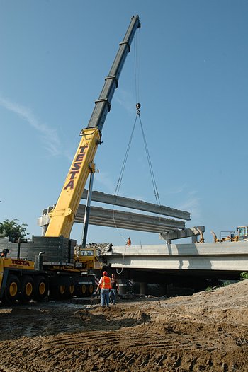
The procedure consisted of attaching cables to each girder, cutting the bolts
that coupled the girder to the caps, lifting the girder, rotating it and then
lowering it. I have tried to capture most of the steps in the procedure.
I shall fill in the details a bit later
Continuation of removing the girders on the east side of the overpass

After all the east girder were removed - here is the I-26 overpass.
First - clean up the debris from removing the roadway between the overpass
girders
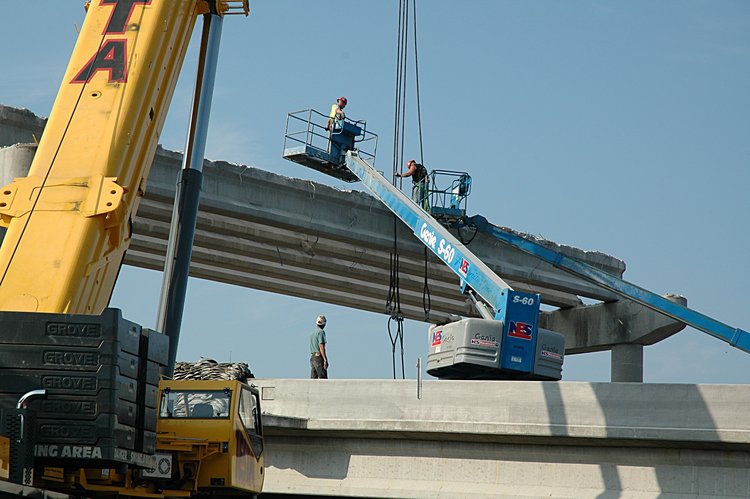
Erecting the crane that will be used to life the girders
Moving the lifting cables into position between the edge girder and the
one next to it

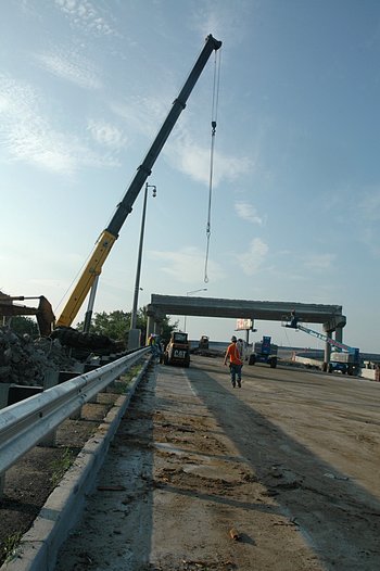
Lowering the cables between the girders

Looping the cables around the outside girder
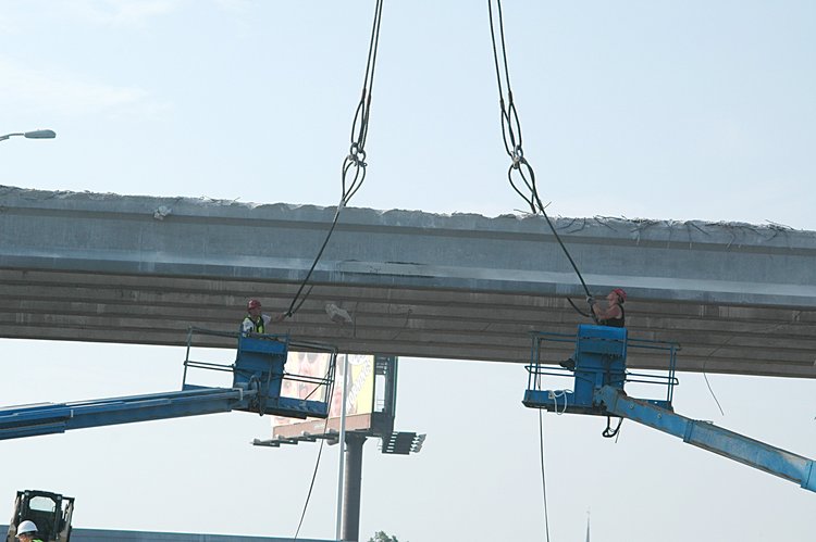
Moving the loops into position
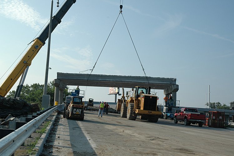
Initial lifting of the girder
the lifting the entire girder
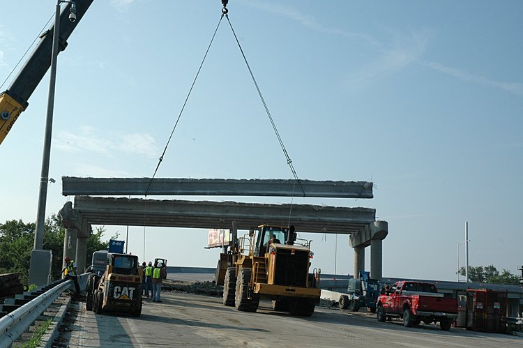
rotating the girder and lowering it to the ground
Decoupling the cable loops
Rotating the lift cables back to the next girder
Positioning the left cables
Cutting the attachment between the girder and the pier cap
An initial lift from below
Then lift - slowly slowly

Rotate and lower

Note the protective blankets placed over the I-26 edge barriers

to the final resting place
Decouple the cable loops

And so it start again with lowering the cables between the next
pair of girders
Making the loops
Raising the loops and moving them into the lift configuration
and so the process starts again
August 14, 2005: Pier extraction
With this addition of these photos,
our bridge story has moved to the next level. Sparky
Witte from Mt. Pleasant grew up here, has walked and bicycled the old bridges
more times than he can count and captured the next phase of removing the I-26
overpass. Here are his photos showing the extraction of one of the pairs
of piers and their cap. As you can see, the Testa guys are not only
surgeons, but also dentists - just imagine a tooth extraction with two
of the Stanley-LaBounty hydraulic units.
Positioning the grapple and shear to start the pier extraction (left)
and cutting the far pier (right)

With the shear, cutting the near pier (left) and a gentle pull from
the grapple (right)

Gentle lowering of the cap and upper pier segments

Continued lowering of the cap and pier segments until the tooth
extraction is complete

Click to view all unbuilding web page segments

This work is licensed under a Creative Commons License.
Attribution: C. Frank Starmer and Sparky Witte from http://oldcooperriverbridge.org


